The Running and Repairing of
|
MODELS
|
E
|
F
|
&
|
G
|
1. WHILE it is not necessary to read this instruction book right through, it is essential before starting a new engine to read those paragraphs marked thus, *, and to see that the crankcase and reverse gearcase contain oil. No subsequent adjustment or repair to the engine should be carried out without reference to the book. Any advice we can give is at your service whether you are the original purchaser of the engine or not. When writing, do not omit to quote the number of the engine stamped on the nameplate, and which should be filled in above.
*2. TOOL BOXES.— A box of tools accompanies each engine. It is closed with a lead seal, and, if delivered with the seal broken, its contents should be checked with the list to be found in the engine catalogue. Provide a convenient dry place for the tool box and hang the following on nails convenient for immediate use :— (a) Finger pin to operate seacock; (b) finger pin and small brass box spanner for the carburettor jet; (c) hexagonal tool to operate the tank deck plate (if supplied).
3. REPLACEMENTS.— All the parts of current models are always in stock, also the parts of our oldest models for which there is a regular demand. Please describe the parts which you require in the terms of the price list which is contained in the tool box. We carry in stock boxes containing a selection of spares suitable for customers in remote districts; contents and price as per price list. To England, Scotland, Northern Ireland, Isle of Man and the Channel Islands, goods not exceeding fifteen pounds (in each package) may be sent by post C.O.D. (cash on delivery). Buyers abroad may have goods sent C.O.D. if they satisfy themselves that the system is available.
4. IMPROVEMENTS.— We make improvements from time to time and, where possible, we make them applicable to engines already despatched. If you wish to know whether any improvements have been added since your engine was made and the cost of supplying them, quote the number of the engine to us.
*5. PARAFFIN.— We are frequently asked which is the best brand of oil for use in a paraffin engine. The question is difficult to answer because merchants sometimes sell different oils under the same brand, and the same oil under different brands. Users in the United Kingdom are advised to write to the undermentioned, asking which of their brands is most suitable for a "Kelvin" Engine, and the name of their nearest authorized agent. Users abroad are advised to try all available brands and select the one which works with least tendency to knock.
Shell Mex. and B.P. Ltd. Shell Mex House,Victoria Embankment. London, W.C.2. Anglo-Persian Oil Co. Ltd. Britannic House, Finsbury Circus, London, E.C.2. Scottish Oils Ltd., 53 Bothwell Street, Glasgow, C.2. Anglo-American Oil Co., Ltd., 83 Albert Embankment. London, S.E.11. *6. LUBRICATION is the most important care of an oil engine. Use only a proprietary oil of good quality and see that it is delivered to you with the maker's seal intact We cannot indicate all the brands which are suitable, but the oils mentioned are used by our customers.
*7. LUBRICATING SYSTEM.— The oil supply is contained within the crankcase below the reach of the cranks. An oil pump supplies a drip nozzle situated above each revolving crank. The splash created lubricates all internal parts. The renewal of the oil should be carried out according to the instruction plate. The crankcase need not be completely emptied until sediment accumulates. When the crankcase is pumped out (10) the oil pump becomes air locked and it is necessary to make sure that it is working before running the engine.
*8. OIL DRIPS.— The gauze strainer which surrounds the foot of the pump is sufficiently close to catch anything which would choke the drip nozzles. Nevertheless it is advisable to inspect the drips occasionally. With the doors removed turn the engine smartly by hand when oil should drip from all the nozzles. The nozzles are removable, they differ in size, each is numbered, the largest should be forward. The nozzles are graded in size to suit a shaft rake of 1 inch in 18 inches. If the engine is installed level or if the rake exceeds 1 in 9. it is advisable to apply to us for new nozzles.
9. OIL PUMP.— The strainer around the foot of the pump is visible when the oil level is below the" empty" mark on the dip rod. Inspect the strainer occasionally to see that it remains clear. The pump valves consist of steel balls and may be inspected by removing the ram. The pump operating rod is removable through the inspection door. The pump is attached through the bottom of the crankcase but it is not advisable to remove it. If the pump is removed replace it so that the shoulder on the ram is on a level with the top of the pump when the ram is at the bottom of the stroke.
10. CRANKCASE PUMP.— This pump has no valves and should be operated as follows :—The cut on the handle must be towards the engine on the up stroke and towards the pipe on the down stroke. If the pump will not start, put a little oil in by the air hole to seal the piston. If a dear glass bottle is held to the discharge pipe the presence of water in the crankcase is easily detected. The spent lubricating oil is best disposed of by pumping it into old bottles to be dropped at sea.
*11. WATER REGULATOR (Paraffin engine).— When the mark is at"full" all the water passes to the cylinder. When the mark is at"slow" a little of the water passes to the cylinder. The remainder goes from the pump direct to the silencer. At full speed it should be just possible to hold the hand on the cylinder head. Attention to the water regulator prevents condensation of paraffin and dilution of the lubricating oil.
*12. STARTING A PARAFFIN ENGINE.—
1 Turn on the fuel at the tanks and turn the carburettor cocks to petrol.
2. Detach the stopping wire.
3. Turn the water regulator to "slow".
4. Drain the carburettors of paraffin, if necessary.
5. Prime the cylinders with petrol.
6. Withdraw the clutch (knob on wheel down) (53).
7. Close the throttle (hand lever down).
8. Retard the ignition
(Lever towards engine for models"E". ) (Lever away from engine for models"F" and"G".)
9. Turn handle smartly for models" E" slowly for"F" and"G".
10. When engine starts, advance ignition half way.
11. When clutch is engaged, advance ignition fully and turn cock from petrol to paraffin.
12. When top of cylinder is hot, move water regulator to "full".
*13. STARTING A PETROL ENGINE—
1. Turn on the fuel at the tank and carburettor.
2. Detach the stopping wire.
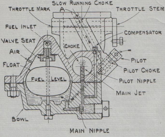
3. Prime the cylinders.
4. Withdraw the clutch (knob on wheel down) (53).
5. Close the throttle (hand lever down).
6. Retard the ignition
(Lever towards engine for models"E") (Lever away from engine for models"F'" and"G".)
7. Turn handle smartly for models" E" slowly for" F" and"G".
8. When the clutch is engaged, advance ignition fully.
Caution.— The clutch must not be engaged with the engine running fast (55).
*14. RUNNING.— The successful running of a paraffin engine depends on keeping it hot. The ignition should not be fully advanced until the engine is under load. The water regulator should be kept at "slow" until the top of the cylinder is hot, when it may be turned to "full". Should the load be reduced either by slowing the engine or by withdrawing the clutch, the ignition should be retarded half way and the regulator turned to "slow". If a four cylinder engine is required to run for more than a few minutes without load, two of the cylinders should be cut out in order to provide more load for those working. This is accomplished by turning the fuel off at the carburettor.
*15. STOPPING.— To stop the engine place the stopping wire on the brass terminal. Take care not to mix the stopping wire with any of the wires to the sparking plugs. The draining of the carburettors may be avoided by turning over to petrol at least one minute before the engine is stopped.
16. ENGINE NOT FIRING PRIMING.— Causes: (a) Overprimed—turn with priming valves open; (b) poor petrol—heat sparking plugs; (c) lack of spark—test plugs (31); (d) stopping wire not detached; (e) magneto contact breaker stuck (35); (f) magneto wrongly set (47 and 48); (g) camshaft wrongly set (49-51); (h) distributor brush worn out (37).
17. ENGINE FIRES PRIMING AND STOPS.— Causes : (a) Lack of petrol—try the carburettor drains; (b) paraffin instead of petrol in the carburettors—drain them; (c) throttle valves not completely closed—see marks; (d) engine over-primed—turn it with the priming valves open; (e) carburettor pilot nipple choked—see illustration and remove it with the tools supplied; (f) carburettor flooding (41).
18. ENGINE RUNS IRREGULARLY.— (a) Sparking plug missing—ascertain which by slightly opening the priming valves one at a time (30); (b) lack of fuel—try the carburettor drains—remove the pilot with the finger pin provided and clear the nipple. Remove the main nipple with the brass box spanner provided; (c) magneto distributor dirty (37); (d) magneto contacts too wide (36); (e) electric cables faulty—renew them.
19. ENGINE RUNNING HOT.— If the cylinders ran more than hand hot with the water regulator full open (handle horizontal). examine the strainer and the valves of the water pump.
*20. ENGINE FLOODED.— The exhaust must discharge slightly above sea level. The silencer must be above the point of discharge. There is no objection to a downward dip in the pipe, but no part of the pipe must be above the silencer. The best arrangement is to give the pipe a gradual fall throughout its length from silencer to point of discharge. If these conditions have not been fulfilled report the arrangement and the engine number.
21. ENGINE LOSING SPEED.— If the loss has been gradual it may be due to an accumulation of soot and salt in the silencer—dean it out—or to the fouling of the vessel below water. A growth not visible to the eye is sufficient to affect the speed. If the bottom is slippery to the hand the boat requires cleaning. It pays to use anti-fouling paint, as the best qualities (all brown in colour) resist growth in a temperate climate for four months—growth begins on ordinary paint in four weeks. There are various makes, but a good brand is obtainable from the International Paint & Composition Company, Ltd., 31 Grosvenor Place, London, S.W.I.
22. REVERSING GEAR RUNNING HOT.— Causes: (a) excessive oil—drain case and put in correct quantity; (b) slipping clutch—due to an obstruction on the propeller or a bent blade; (c) heat generated at the rear bush (23).
23. BUSH AT REAR OF REVERSE GEAR RUNS HOT.— Causes: (a) lack of oil due to oil leakage (24)—renew oil according to instruction plate; (b) shafts out of line—remove shaft coupling and check alignment of shafts with a steel rule or the blade of a carpenter's square (57). 8 levelling washers were supplied to be used below the engine as the foundation shrinks (75).
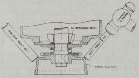
24. REVERSE GEAR LEAKING OIL.— Causes: (a) bottom flange not tight or joint defective; (b) breather pipe obstructed; (c) oil retaining joint at rear end of crankshaft directive (54).
25. CLUTCH SLIPPING.— Causes: (a) Propeller blade bent; (b) shaft out of line (23); (c) propeller of excessive pitch—Report engine number, dimensions and speed of boat, r.p.m. of engine with throttle held full open.
26. ENGINE KNOCKING.— If the knock is within the crankcase, look for something loose, misplaced, or hot. If the knock is within the cylinder, and only when running; at full speed, it may be due to (a) the quality of the fuel—try another brand (5); (b) excessive soot within the cylinders—remove the heads (62); (c) too heavy a propeller (67).
27. PROPELLER SHAFT VIBRATION.— Causes: (a) Lack of clearance between propeller and woodwork (28); (b) slackness of shaft in stern tube due to wear (66); (c) propeller blade bent; (d) shaft out of truth (57); (e) shaft bearings slack, file the lower half.
28. PROPELLER INEFFICIENCY.— Causes : (a) Lack of clearance between propeller and woodwork—increase the aperture wherever possible; (b) stern post too clumsy—reduce it as much as possible; (c) rudder post too thick—reduce or abolish it; (d) diameter or pitch of propeller not suitable. Report the engine number, length, beam, and, if possible, the speed of the boat, also the full speed of the engine.
29. BILGE WATER.— If water is permitted to reach the crankshaft at the back of the flywheel, rust will occur, and the white metal bush in the lower starting wheel will be damaged. As this cannot be easily rectified, it is important to allow no water to reach the flywheel.
30. SPARKING PLUG MISSING.— If due to soot bridging the gap, it may be cured without stopping the engine by detaching the terminal from the plug and holding it, by the cable, at some distance from the plug. The long spark thus produced intensifies the electric current. If missing is due to soot within the body of the plug, take it to pieces. If due to causes described in par. 32, throw it away.
31. SPARKING PLUG TEST— Take out plug, lay it on engine so that its body alone makes contact, turn the engine by hand. If no spark results (33).
32. SPARKING PLUG, CARE OF.— Porcelain plugs must be handled with care. A spanner carelessly applied may produce in the porcelain an invisible crack which in time holds moisture and causes the plug to short. The thread of the sparking plug should be oiled.
33. SPARKING PLUG ADJUSTMENT.— The spark gap becomes wider with use, and the points should be bent to maintain the gap at .5m/m or .020 inch (gauge attached to magneto spanner). The size of the spark is in proportion to the width of the gap. A spark too small may fail to start the engine, but a gap too wide may fail to produce a spark. A plug which sparks in the open air may not do so when exposed to the pressure within the cylinder—such a plug may start the engine if the priming valves are kept open. If the magneto is suspected of being weak keep the gap of the sparking plugs rather close—a small spark is better than no spark.
*34. MAGNETO, CARE OF.— Allow no oil or paraffin to drip on to the magneto as that causes rapid wear of the platinum contacts. The magneto requires only three drops of oil once a month.
35. MAGNETO CONTACT BREAKER.— The moving arm of certain makes is liable to become stuck in damp climates owing to the swelling of its fibre bush. Remove the arm, polish and oil the pin; scrape out the fibre bush with the square tail of a small file or other suitable instrument. The fibre pad on the end of the arm should be oiled, but no oil must reach the platinum contacts.
36. MAGNETO CONTACT BREAKER GAP.— The contact points are platinum tipped and gradually wear further apart, with the result that the gap increases. A gauge is attached to the magneto spanner; try it in the gap, and, if necessary, adjust the screw. As this adjustment is difficult to carry out, it is advisable to keep a spare contact breaker. If the contact points wear rapidly.
37. MAGNETO DISTRIBUTOR.— Some distributors have carbon brushes which wear. The dust produced must be removed from time to time. When the brushes wear down they should be renewed; the stretching of the spring serves temporarily.
38. MAGNETO REPLACEMENTS.— Owing to the great variety of magnetos which we have been obliged to supply, we cannot keep stock of all magneto replacements, and buyers are advised to communicate direct with the magneto maker, taking care to quote the number of the magneto if it bears one. A magneto sent to the maker should be labelled with the owner's name, and its despatch advised to the maker.
BOSCH MAGNETOS. Bosch Limited, Larden Road, Acton, London, W.3. SIMMS MAGNETOS. Simms Motor Units Ltd., Oak Lane, East Fincley, London, N.2. B.T.H. MAGNETOS British Thomson Houston Co., Ltd., Alma Street, Coventry. *39. WATER PUMP STRAINER.— This should be cleared regularly. A finger pin to operate it is supplied. This should be hung on a nail convenient. The strainer requires little attention at sea, but frequent attention if the engine is run with the boat at rest in shallow water, especially if the reverse gear has been in action, as that stirs up the water. It is important to know immediately if the strainer has become choked—one method is to feel frequently the water pipe from cylinder to silencer. A better method is to coat with oil paint the exhaust elbow below the silencer. Immediately the strainer becomes choked, the water fails and the paint on this elbow creates a smell which warns you to stop the engine.
40. CARBURETTOR FUNCTIONS (see diagram).— The function of a carburettor is to impregnate, with fuel, the air on its passage to the engine. The fuel enters where shown, and its level is controlled by the float. When the throttle valve is closed, air enters through the pilot, meets fuel coming through the pilot nipple and passes to the engine by the hole A. When the throttle valve is opened air rushes through the choke and causes the main jet to spray. The slow running choke controls the speed of the engine when the throttle is closed. The pilot choke and pilot nipple control the strength of the mixture for slow running. The main nipple controls the strength of the mixture at running speeds, and the compensator prevents the mixture becoming too strong. The fuel which runs back from the throttle valve at certain speeds is returned to the bowl by a drain hole not shown The numbers stamped on the nipples represent their capacity. Never tamper with the orifice. If you wish to experiment, get additional nipples from us. The number of the original is stamped beside it.
41. CARBURETTOR FAULTS.— Stoppage of the pilot nipple causes difficulty at starting, and irregular running at low speed. Stoppage of the main nipple causes irregular running at higher speeds. Stoppage at the valve seat may cause any of these conditions. Avoid bending the fuel pipe between the filter and the carburettor as that liberates scale which may choke the valve seat. Stoppage of the compensate causes the mixture to become too strong at high speeds. Leakage at the needle valve causes flooding, choking and difficulty at starting. If the throttle valves do not close together, the engine will fire irregularly when running slow.
42. THROTTLE VALVES (Model G).— When the brass governor lever is hard down on the case, the throttle valves should be all exactly closed—marks coinciding.
43. CARBURETTORS CORRECT.— If the throttle valves and carburettors are properly adjusted, the engine will fire steadily at all speeds, and will not be affected by (a) a rake of shaft up to 1 in 9 ; (b) a list to port or starboard of 25 degrees; (c) a tank at any height up to 8 feet above the fuel inlet.
44. IMPULSE STARTER PRINCIPLE (Models F and G). — Revolving with the magneto spindle are two pawls, which project when the engine is standing and recede when the engine starts. The projection of these pawls engages with a latch. The engagement of the pawl with the latch arrests the rotation of the armature and stretches a pair of springs. At a certain point the latch releases the pawl, and the springs impart to the armature a rapid motion which causes the magneto to produce a spark however slowly the engine is turned.
45. IMPULSE STARTER TEST S.— When the engine is turned by hand the impulse starter should produce a click twice per revolution. The action may be observed by removing the cover from the end of the magneto. If the device is not working remove the magneto.
46. THE GOVERNOR (Models G2 and G4).— The throttle valves are opened by a spring and closed either by the hand lever or by the governor. The throttles should always be closed by hand before the clutch is either engaged or withdrawn. If the clutch should become disengaged with the throttles open, the governor will close them. The speed at which the governor acts depends upon the number of weights on its arms. The governing speed should be a little higher than the maximum at which the engine can drive the propeller. As we cannot estimate this speed, it may be necessary for you to alter the governing speed. To lower the governing speed, add four weights. To raise the governing speed remove weights—always four at a time to preserve the balance.
47. TO SET MAGNETO (Models E).—
1. Remove the covers from the magneto case and the end of the magneto.
2. Retard the ignition (hand lever towards engine).
3. Slacken the 4 screws securing the chain wheel
4. Turn the engine until No. 1 priming valve blows, and the mark on the flywheel is central (firing position).
5. Lay No. 1 sparking plug, with its wire attached, on the top of the engine.
6. Turn magneto in the direction of rotation (see mark) until the plug sparks—oscillating it slightly to help the spark.
7. Tighten the 4 screws so that the contact breaker is exactly in the act of breaking.
48. TO SET MAGNETO (Models F and G).—
1. Remove the covers from the magneto case and the end of the magneto.
2. Retard the ignition (hand lever up).
3. Slacken the 4 nuts securing the chain wheel.
4. Turn the engine until No. 1 priming valve blows, and the mark on the flywheel is central (firing position).
5. Lay No. 1 sparking plug, with its wire attached, on the top of the engine.
6. Turn the magneto in the direction of rotation (see mark) until the plug sparks—oscillating it slightly to help the spark.
7. Tighten the 4 nuts so that the contact breaker is exactly in the act of breaking.
8. Insert the impulse spring before replacing cover.
49. TO SET THE CAMSHAFT (Models E2 and F2).— Bring No. 2 crank up and the mark on the flywheel central. Turn the camshaft until a mark on the shaft is visible at a hole in the gunmetal bearing. Put on the chain. The firing rotation is 2-1-0-0.
50. TO SET THE CAMSHAFT (Model G2).— Bring No. 1 crank up and the mark on the flywheel central. Turn the camshaft until a mark on the shaft is visible at a hole in the gunmetal bearing. Put on the chain. The firing rotation is 1-2-0-0.
51. TO SET THE CAMSHAFT (Models E4, F4 and G4).— Bring No. 1 crank up and the mark on the flywheel central. Tun the camshaft until a mark on the shaft is visible at a hole in the gunmetal bearing. Put on the chain. Repeat the operation with No. 4 crank but before doing so give the flywheel one complete turn. The firing rotation is 1-2-4-3.
52. TO DISMANTLE REVERSING GEAR.— Remove the cover, find the spring link in the chain, remove the chain, detach the case from the engine. If the ball thrust bearings are removed, see that they are assembled correctly. In models F and G the two washers differ in size. Look out for the words "large washer" stamped on the end cover and on the astern clutch.
53. TO REPLACE REVERSE GEAR CASE.— Fix the case to the engine.—Draw in the chain by means of a copper wire passed around the lower wheel. When the chain engages the lower wheel help it around by turning the engine gently. Replace the spring plate on the chain so that it runs closed end first. Permit nothing to fall into the gear case—keep it covered. If the spring plate is dropped into the case it may be recovered by the bottom flange. Mesh the control chain so that shaft is at mid-travel (neutral) with knob of wheel down.
54. CLUTCH.— To remove the clutch from the crankshaft without damage, proceed as follows :—Remove the nut which retains the clutch, hold a heavy iron bar (like the stock of an anchor) against the clutch on the port side while using a heavy hammer very lightly applied on the starboard side.
55. CLUTCH, WORN OUT.— Causes : (a) Manipulating the clutch without first slowing the engine ; (b) running with the clutch supping (25).
56. CHAIN JOINING LINK— Each chain has a joining link secured by a spring plate. See that the spring plate is properly in position, and carry a spare spring plate, as they are very easily lost in handling. The spring plate should be put on so that it runs closed end first.
*57. SHAFT COUPLINGS must be very tight. If once they slip both coupling and shaft become torn and ruined. All parts of the shaft coupling should be painted before being assembled. If shaft runs out of truth it is probably due to unequal tightening of shaft coupling bolts. Hold a pencil to the running shaft and tighten the bolts at the side marked by the pencil.
58. THE CAMSHAFT.— Each pair of cylinders has its own camshaft, running in bearings attached to the underside and removable along with the cylinders. The camshaft is driven from a lower shaft which is in turn driven by chain from the crankshaft. If the camshaft or the gear wheels are dismantled reassemble them according to the marks. If the chain is removed the camshaft must be reset as per instruction plate. The chain should be tightened when the sag amounts to 1/2 in the case of models E, 3/4 in F, 1 inch in G. This is done by inserting an additional joint below the cylinder. When three joints are necessary the chain should be renewed.
59. VALVE INSPECTION.— The valves should be removed for inspection after 500 hours of running. If the seat does not show a bearing all round, apply a little of the grinding paste which will be found in the tool box, while rotating the valve to and fro lightly with a screw driver.
60. VALVE ADJUSTMENT.— Between the lower end of the valve stem and the plunger a slight clearance is necessary. For the adjustment of this clearance, you will find in the tool box a gauge, also a spanner thin enough to go between the coils of the spring. This clearance should be as follows :—
You will observe that the inlet valves are sunk in their seats or "masked" as it is called. The depth of the mask must not be altered.
61. PISTONS.— Inspect one of the pistons every six months of running to see that the upper ring is free in its groove (77). Have a spare ring at hand before doing so. The upper ring stuck fast is harmful to the cylinder and is a sign that the lubricating oil is bad (6). To remove a piston first dismantle the oil drip pipe, then detach the connecting rod from the crank and the piston will come down and out by the inspection door.
62. THE CYLINDER HEAD.— Before removing the cylinder head drain the water by the brass drain screw, then remove the nuts and screw down the eye bolt which will be found in the tool box. This will start the joint. Before replacing the cylinder head remove the eye bolt and see that the rubber joints around the water bushes are in good condition (important) If not, renew them. If you have no replacements use cotton twine soaked in oil paint. Joint with the cement to be found in the tool box or obtainable from motor dealers. Oil the studs before screwing down the nuts. The eye bolt is strong enough to lift the engine. Keep it in the tool box and close the hole with a cork.
63. CRANKSHAFT runs in suspended bearings lined with loose white metal bushes—easily adjusted—all bushes alike. The bushes should run a year without attention. To tighten a bush file the flat flange of the lower half until the tightening of the bolts binds the shaft, then scrape the inside of the lower half until the bolts can be thoroughly tightened without binding the shaft. The upper half must not be scraped, interchanged, or replaced, without checking the whole alignment of the shaft, which can only be properly done with the crankcase upside-down, but the upper halves should develop no wear. A little red lead and oil applied to the crankshaft shows up the parts in the bush which require the scraping. When all the bolts arc thoroughly tight the crank should be sufficiently free to be turned by one hand applied to the taper end.
64. BIG END.— The big end of the connecting rod is fitted with loose white metal bushes. The adjustment of a bush should be carried out with the other connecting rods removed. To tighten the bush file the flat flange until the tightening of the bolts binds the shaft, then scrape the inside of the lower half until the bolts can be thoroughly tightened without binding the shaft. A little red lead and oil applied to the crankpin shows up the parts in the bush which require the scraping.
65. FLYWHEEL.— To remove the flywheel take off nut, strike end of shaft with a heavy hammer while applying a piece of wood behind wheel as a lever. Protect end of shaft with a piece of copper or brass while striking it.
*66. STERNTUBE.— A Cutless rubber bearing is fitted on the outside. It requires a through circulation of water which enters by two little pipes. The sternpost must be trimmed down to bring these pipes into the stream line. As rubber does not stand grease, the shaft must be inserted dry and the packing must be impregnated with graphite and the minimum of grease. As the graphite is dissolved out of the packing in time, it is desirable to renew the packing once a year.
67. PROPELLERS should be removed with a heavy hammer—a light one harms the propeller without removing it. Secure the nuts with a turn of monel wire through the end of the shaft. If you consider the propeller unsuitable for your boat, report to us the length, beam and draught of the boat, the speed of the engine with the throttle held fully open, and the markings on your propeller.
68. TANKS.— A tank aft of the engine must have a margin of height to allow for the sinking of the stem when the launch is under way. Petrol tanks are dangerous below deck where lamps are ever present, and should be installed where exposed to the open air. Tanks should be painted before being fixed. Each tank is fitted with a device to warn you when it is nearly empty. You are safe to run until the engine begins to hesitate. If you slow the engine at once, it will keep running while the tank is being refilled.
69. BALL BEARINGS.— The failure of ball bearings is seldom due to fair wear or to original defect, but almost always to lack of protection from damp or to defective mounting. As soon as the burnished surface of the balls shows rust the failure of the bearing is imminent.
70. JOINTS.— Each boat should carry a stock of joints obtainable from us. In cases of urgency, joints may be cut from certain materials obtainable from mill furnishers or motor dealers. For exhaust use "asbestos millboard" coated with graphite or black lead to prevent adhesion ; for water use "rubber insertion" ; for oil use white of egg or Shellac or any of the cements sold by motor dealers. Red fibre withstands oil and water but not heat. India-rubber withstands water but not heat or oil.
71. FROST.— In severe weather the water should be drained from the jackets by the drain screw. The sea-cocks must be closed and the floor boards should be left open to remind you to open the seacocks before starting. If the drain screw will not hold tight don't abuse it with the pliers. Renew the cork inside it.
*72. DECK CONTROL.— For leading the control of the clutch and throttle on deck or into the cockpit, a variety of fittings are kept in stock. Catalogue on request.
73. CARE OF ENGINE.— Kelvin engines are designed to be easily kept clean—all parts are rounded—no sharp edges. Use cotton waste obtainable from chandlers—old cloth is not suitable—keep your waste dry. Wipe your tools each time you use them.
74. WINTERING.— Before laying up an engine for the winter it is important to remove any salt dried on to it, as this draws damp and causes an excessive rusting action. To do so, wash down the engine with hot water. Drain all the water from the cylinders, pumps, and from any pipe bend where water can lie. Pour some lubricating oil into each cylinder, and turn the engine by hand. Grease everything not protected by paint. As a wooden vessel exudes moisture inside for about 6 months after being hauled up, it is necessary to provide continuous ventilation if excessive rust is to be avoided.
*75. ENGINE FOUNDATION.— All Kelvin models are designed to rest on two transverse bearers (longitudinal bearers are not suitable). The bearers must be of hardwood and should rest direct on the planking clear of ribs. In boats having only steam-bent ribs the bearers must run up the bilge to the height of the flywheel centre, but in boats with grown frames the bearers may be straight on the upper surface. The bearers should be fastened from outside with brass screws and drawn hard down to the keel with a proper brass screw bolt which should be tightened once a year as the wood shrinks. 8 levelling washers were supplied with the engine. One at least should be below each foot to prevent it sinking into the wood.
76. SPEED IN RELATION TO POWER.— Resistance of a vessel to propulsion is due to two distinct causes—surface friction and wave making. Surface friction is present at all speeds. Wave making is absent at a low speed, commences suddenly and increases rapidly. It follows, therefore, that any boat is easily driven up to its wave-making speed, and beyond that only by an extravagant expenditure of power. If economy in first cost or in running expense is of importance, it is advisable to instal only sufficient power to produce the wave-making speed. It is a common fallacy that a vessel with good lines must be easily driven. At low speeds the lines count for nothing, because surface friction is the whole source of resistance. At higher speeds what counts is the relation between the displacement (weight) and the water hue length. It follows that an increase of speed should be sought by decreasing the displacement or increasing the length rather than by increasing the power. These remarks will explain why heavy short high-powered craft are disappointing in speed.
77. OVERHAUL.— A hardworking engine should be overhauled once a year and the overhaul should be sufficiently extensive to make every part good for another year's service. The practice of running an engine until trouble develops is equivalent to overhauling by instalments—a costly method. Before starting the work, dear all surplus gear out of the engine room, provide, if possible, a work bench, a paraffin wash tray, and cotton waste. Wash down the engine with paraffin to slacken the nuts and soften the rust. Proceed as follows and order the replacements necessary by telegraph to avoid delay.
Withdraw the pistons down through the inspection doors. Order new rings to replace any which are more than '008" slack sideways. If the piston bushes are slack, order new pistons, or send the old ones to us to be re-bushed. If the cylinders are worn more than .003 per inch of diameter, renew them, or send them to us to be lined. If this is done both the pistons and the rings should be renewed. Remove the heads and order new joints. Withdraw the valves and renew or re-machine any which are badly worn. If the valve seats cannot be restored by grinding, apply to us for a cutter on loan.
If the sag of the camshaft driving chain amounts to 1/2 in models E, 3/4 in models F, or 1 in models G, it should be tightened by the addition of a joint below the cylinder. When three joints are required, the chain should be renewed. An estimate of the number required may be made by slackening the studs and prising up the cylinder until the chain is tight. Inspect the cams and plungers.
Remove the water pump, examine the seat of the suction valve and, if badly worn, have it re-faced. Add a turn of packing if there is room for it.
Take the cover off the reverse gear and order a new chain if it shows evidence of striking the case. Detach the shaft coupling, examine the ball thrust bearings and order replacements if they show evidence of rust. Remove the reverse gear case and ascertain whether the ahead clutch is secure on the crankshaft.
Remove the contact breaker from the magneto by detaching the central screw. Examine the platinum contacts, and if they are too much worn to be restored by tiling, order renewals. Remove and clean the distributer and order a new carbon brush, if necessary.
If the starting chain is very slack, remove the flywheel (65) and examine the white metal bush in the lower starting wheel. If it, or the shaft, are badly worn, renew the bush and take some steps to guard against water reaching this part (29).
If there is evidence of oil escaping at the crankshaft at the front end, remove the cover and renew the cork washer. Adjust all the bearings (63 and 64). Adjust the valves (60).
Remove the oil drip nozzles and clear them. Clean the filter of the oil pump.
Dismantle the carburettors completely and see that all the jets and passages are dear. Clean the fuel filters.
If the magneto wires are in bad condition, order cable to renew them.
The packing in the shaft stuffing boxes should be taken out and renewed.
Check the alignment of the propeller shaft. This is very important in the case of engines installed far aft.
Scrape the rust off the engine and the tanks and repaint with "KELVIN" paint.